
 English
 中文
中文


In general, the application of flexible circuits is only limited by our imagination. One of my favorite jobs is to be able to discuss the design of flexible circuits and rigid-flex boards with a group of engineers and designers. During the “lunch and study” time, we will jointly study technology trends or solve a specific problem. Bringing samples between engineers to showcase and show different characteristics of the sample is very helpful for learning communication. Observing a sample can be inspiring and get advice from others. "I want to know if we can make products like this." Brainstorming started from that moment.
I learned that this month's theme is "everything starts with design," and I want to know if I can inspire people by looking at pictures rather than flexible circuits and rigid-flex boards. If these images help to generate a new design idea, I would love to hear it. If not, I will point out that some of the best methods in these designs should benefit those who are new to flexible circuit and rigid-flex board design. For those who already have rich design experience, they will also have good results. Inspiration.
Let's start with the basic flexible circuit design. Figure 1 is a simple one-sided design that connects two components. I think flexible circuits can replace wires to save space and weight. It can also replace rigid boards to solve packaging problems. The FR-4 stiffener is very important here to support heavier components and prevent damage to the flex circuit.
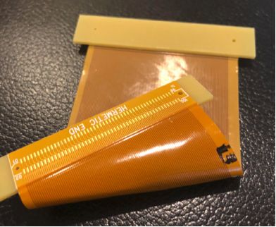
figure 1
Figure 2 is a double-sided flexible circuit that includes through-holes and SMT components. In this picture, you can see the polyimide reinforcement plate in the tail area. The Zero Insertion Force (ZIF) connector is a common method of terminating flexible circuits with tight tolerances on form factor and total thickness. Polyimide reinforced sheets are commonly used to increase thickness to meet technical specifications.
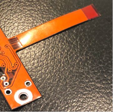
figure 2
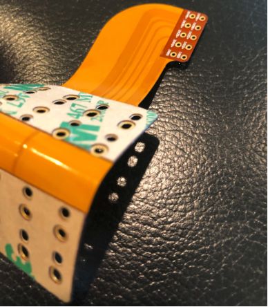
image 3
Figures 4 and 5 are pictures of a double-sided flex circuit that makes good use of the advantages of flexible circuits in installation. The shape of the flexing interconnect is creative and imaginative. In Figure 4, it is conceivable that this flexible circuit can be easily mounted into the housing instead of wires and components. In Figure 5, it is also conceivable how the tail is separated from the main flexible region. What you can't see is that the PSA will be used to boot and fix during the installation process.
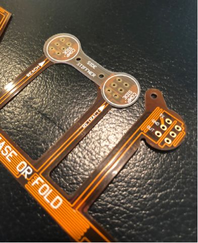
Figure 4
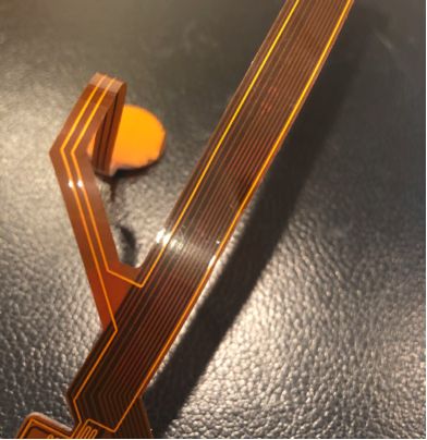
Figure 5
Image 6
Figure 7 is also a rigid-flex plate design with circuitry in the rigid region. The design also uses a loose-leaf structure that does not use thick copper but has 10 flexible layers. If the 10 layers are all bonded together, the flexibility required for the end application cannot be achieved. A cross-shaped shield is applied to the flexible layer to increase the flexibility of each layer.
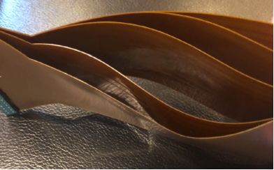
Figure 7
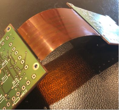
Figure 8
Figure 9 is another example of a rigid-flex plate structure showing how the flexible tail region can aid in packaging. Packaging is becoming more and more important as we face the challenge of installing more complex electronic products into smaller and smaller spaces. The example also shows a crisscrossed copper pattern in the bend area, improving the bendability.
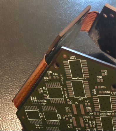
Figure 9
Figure 10 is a complex rigid-flex design that separates the various tails from the main bend zone. This is an example of a good use of imagination and rigid-flex combined bending ability. The cross copper pattern can also be seen to improve the bending of the flexible circuit. What is not visible is the increased stress relief in each flexible tail region. This design will eventually enclose four different curved and folded regions, and the tail will be routed in all directions.
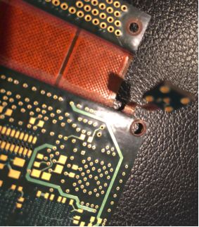
Figure 10
Figure 11 is a final rigid-flex design showing the power of flexibility and potential for packaging solutions. It is conceivable that such a rigid-flex plate can bypass a fixed portion from above when connecting a complicated electronic device. This is an excellent example of solving packaging problems with rigid-flex boards.
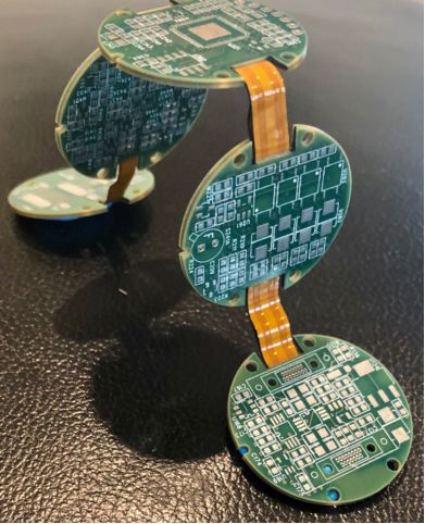
Figure 11
The flexible and rigid-flex panel design allows engineers and designers to be both creative and scientific. It is hoped that designers will see these examples and help them to develop design ideas and develop creative solutions to help them solve space, weight and packaging constraints with flexible circuits and rigid-flex boards.